To this point we have been focusing our instruction on orthographic projection. In an orthographic projection at least two views are always required to completely define an object. In orthographic projection, each view only shows two dimensions. For example, the front view of an object shows only height and width, the top view shows only width and depth and the side view shows only height and depth.
Learning to read orthographic projections takes practice and instruction. To aid in instruction we have been using isometric projections of objects. Isometric projections provide visual description of the object with one view. An isometric projection can typically be interpreted by individuals without any specific training or instruction in the reading of engineering drawings.
Isometric projection is a type of orthographic projection. Consider the glass box: In normal multi-view orthographic projection, the object is placed inside this imaginary glass box so that the principal faces in the object are parallel to the faces of the glass box. In isometric projection the object, instead of having its faces parallel to the plane, is rotated and tilted in such a way that all the principal faces on the object are inclined. The projected views are then drawn connected so that they form an object. Compare this to multi-view orthographic projection, in which the views are drawn separately. Isometric sketching is particularly useful for displaying conceptual design features on paper and communicating those features to others. Isometric sketching is a skill that takes time and practice to develop.
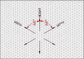
Initially the use of isometric paper will be of great assistance in making isometric sketches. Isometric paper has lines dividing the paper into small equilateral triangles. Since an isometric projection of an object will show that object in a three dimensional view, the isometric graph paper must have three axes. One of these axes is a vertical line. The other two axes make angles of 60 degrees with the vertical. In plotting size dimensions, the height of the object is measured along the vertical axis, with width and depth measured about the axes at 60 degrees to the vertical. The size of the equilateral triangles created by the intersections of these three axes represents dimensional units to be defined by the creator of the drawing. In order for the isometric drawing to be proportionaly accurate to the object being represented, the units in each direction must be consistent. In other words, if each unit on the vertical direction is defined to be 1/4 of an inch then each unit in the depth and width direction must also be defined as 1/4 of an inch.
To begin an isometric drawing it is usually helpful to start with a rectangular cube that defines the overall height, width and depth of the object. This rectangular cube would be sketched very lightly, as many of the lines creating this rectangular cube will not be a part of the completed drawing. In the isometric view, three planes on this rectangular box will be visible. If those three planes are taken to be the three principal views given in an orthographic projection, the transition from the orthographic projection to the isometric becomes quite simple.